The Care and Feeding of My Pet Arduino
by Budd Churchward - WB7FHC - NIBBLES AND BITS LIBRARY
Sequencing RGB LEDs
« 1 2 3 4 5 6 »
|
|
Nibbles and Bits
The Care and Feeding of My Pet Arduino by Budd Churchward - WB7FHC - NIBBLES AND BITS LIBRARY Sequencing RGB LEDs« 1 2 3 4 5 6 » |
Section 3 - Populating the Breadboard
|
OK, so we're putting together a simple project that will
light our LED with a different color every time we press a button.
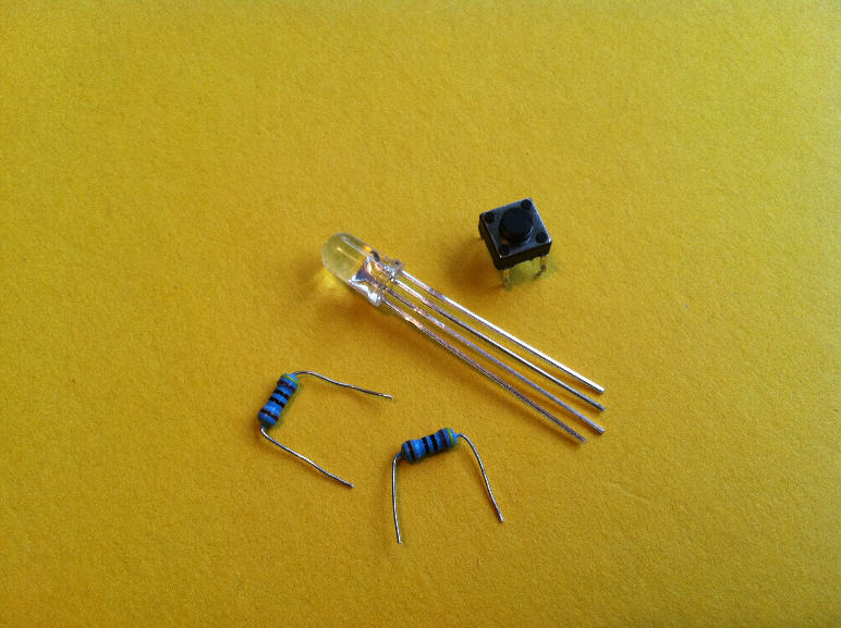
So here is a quick review of the components we will need:
|
|
|
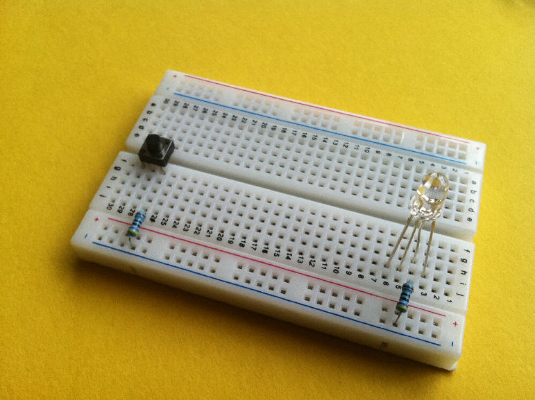
Begin by pressing the mini switch into the bread board. It will fit straddling
the center gap between the board's two halves. If it doesn't fit, give it a quarter
turn.
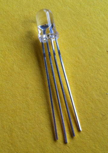
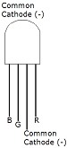
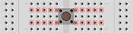 Note: this links the gangs of points on opposite sides of the board as shown. At the other end of the board, insert the four pin LED. The cathode is longer than the other three pins. I had to bend it back a little to compensate for it's length. Spread the other pins apart slightly to match adjacent holes in your board. To get my LED to fit nicely I found it easier to put all the anodes in one column and the single cathode into the column behind them. The bonus here, is that it makes identifying the cathode easier on the board. Most breadboards give us two long busses of points along each edge. On my board you can see that they are labeled with red and blue lines. I will take advantage of these and bring 5v and ground to them. Watch out for some longer boards. They include busses like these that are segmented and don't run the full length of the board. It is quite common to install short permanent jumpers if you want the bus to run all the way. We install the two resistors next. Link the row of points shared by the cathode of the LED to ground bus with one resistor. Link the row of points connected to one of the mini push button pins to the ground bus with the other resistor. |
|
|
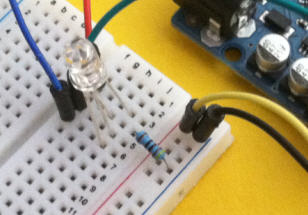
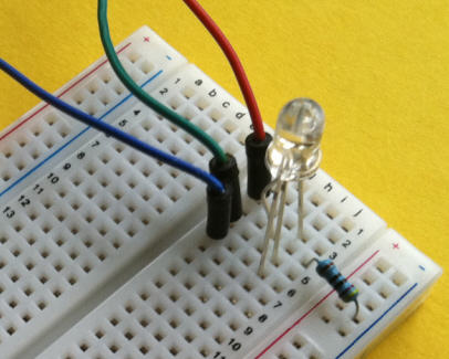
I have chosen three jumper wires colored
red green and blue
to match the anodes on the LED. You can see how I have hooked them up in the close-up photo.
Click the photo for an expanded view that shows all the components. |
|
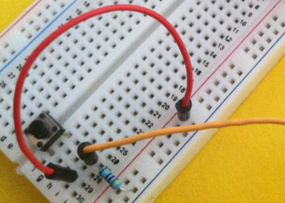
| Run a short jumper from the second terminal of the switch to our 5v bus (shown in red in the photo). Then add a longer one (orange) that will end up attached to one of Arduino's digital pins. We pin it down between the right hand terminal of the switch and our pull down resister so that they are all hooked together in one common row of holes. |
|
|
To provide power and ground to the breadboard I have hooked up a yellow and black
jumper to the end of the two busses. The yellow will go to 5v. The black goes to
ground.
|
|
 The breadboard is ready to go. In the next section we will hook up Arduino's side
of the project.
The breadboard is ready to go. In the next section we will hook up Arduino's side
of the project.