The Care and Feeding of My Pet Arduino
by Budd Churchward - WB7FHC - NIBBLES AND BITS LIBRARY
Sequencing RGB LEDs
« 1 2 3 4 5 6 »
|
|
Nibbles and Bits
The Care and Feeding of My Pet Arduino by Budd Churchward - WB7FHC - NIBBLES AND BITS LIBRARY Sequencing RGB LEDs« 1 2 3 4 5 6 » |
Section 2 - Resistors
|
In this section we are going to review 'limiting resistors' and 'pull down resistors.'
These are components that you will use often in your projects. We will take a brief
look at why we need them. If you already know about this, you should skip ahead now
to Section 3.
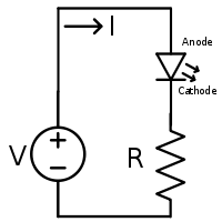
Why Limiting Resistors? It's all about the LED. LED stands for: light emitting diode. It is important to remember that an LED is a diode! What diodes do is allow electricity to flow through them unencumbered in one direction but completely block the flow in the opposite direction. By unencumbered, I mean 'with next to no resistance.' |
|
|
Next you need to be sure you understand who the players are here. We've got resistance [R], which we
have already mentioned. We have current [I]. And, of course, we have voltage [V]. The big gun in this
trio is current not voltage as you might be inclined to think. If you stick your finger
in an amplifier where you shouldn't and get zapped. It isn't the voltage that makes you jump.
It's the current.
Having said that, there is a predictable relationship between the three. A long time ago, a German named Georg Ohm figured this out. His discovery was so important that they named the unit we used to measure resistance after him. To learn more check out: Ohm's Law. So, it is the current [I] that is doing the work. Ohm's Law says that current can be calculated by dividing the voltage by the resistance [I=V/R]. In simple terms: the less the resistance the greater the current. Without a resistor in the circuit, the internal resistance of the LED is so low that we are nearly dividing by zero! This means that the current is going to be excessive and you are going to fry the insides of your LED. |
|
An LED would like to see something between 10 and 20 milli amps of current to function well over a long lifespan.
We can do some simple math to figure out what value the resistor should be. Another version of Ohm's Law says
that resistance is equal to the voltage divided by the current [R=V/I].
 This means that when using Arduino's 5v power we want a resistor some where around 250 Ω to 500 Ω.
|
|
|
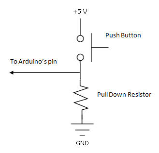
Why Pull Down Resistors? When we press the button in our project, we are going to apply 5v to one of the input pins on Arduino. He will see that and turn on the LED. When the button is up, we have to do something with that pin. We can not just leave it unattached or 'floating' as you will often hear. With a supply voltage of 5V, a low input cannot be greater than 1.5v, and a high input must be greater than 3.5v. Anything between the two can have an erratic effect confusing Arduino so he bounces between high and low willy nilly. Typically, pull down resistors have much higher values than what I have chosen to use here. 1K Ω, 5K Ω, even 10K Ω are better values. For this project I chose to make the two resistors the same value so that I didn't have to worry about which one went where. When the button is pressed some of the current is going through the resistor to ground, but most of it goes right to Arduino's pin. The with a greater resistance less current is spent. If this were a serious battery operated project, our 470 Ω resistor would be a very poor choice. |
|